


Mahogany Ripples
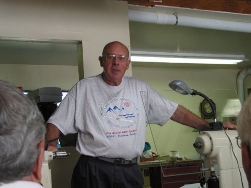
At the September 20, 2003 meeting Bill Haskell from Placentia, CA demonstrated his technique for making sculptural, multi-center faceplate turnings. Below is an outline of his technique illustrated with photos corresponding to the numbers in the text below. Photo credits to Ron Lindsay, Bill Haskell and David Frank. Photo #1 is of President Al Geller introducing Bill. See www.homestead.com/bhask for examples of Bill’s work and details about his background and galleries where his work is shown.
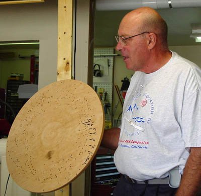
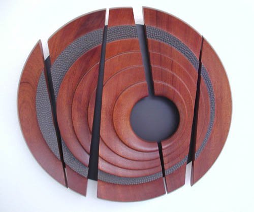
Bill (#2) started by discussing the inspiration for his wall sculpture from a David Ellsworth comment and the work of Tex Isham (#3). Tex mounts his work on a lathe but never turns the lathe on, and uses an x/y table-mounted router to achieve his unique designs while hand rotating the piece on the lathe. Bill wanted a three-dimensional sculptural wall hanging that he could make with the lathe turned on. He came up with a design that involves hours of planning and preparation prior to the actual turning process. Bill showed a commercially available jig that allows for slight off-center or eccentric work on small pieces (#4, 5), but Bill wanted to be able to make large pieces like the example he brought (#6). He uses a 19″ diameter plywood disk mounted to a faceplate as a jig (#7). The mounting holes are predrilled for each position that the work piece will take on the jig; index marks are made to help with alignment (#17). This also allows the work to be replaced into previous positions if he wishes to rework or re-sand an area.
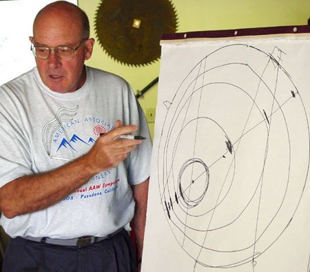
At the easel Bill diagramed the design concept (#8). He uses 1½” x 6″ to 8″ stock (usually mahogany or other wood without prominent or distracting grain pattern). Using templates made from the preplanned design, he cuts the segments (the straight lines in the diagram) that are jointed or disc sanded to fit perfectly together. These are glued together only at the outer edges so that, after the work is finished on the lathe and the outer ring is cut off, the segments will separate easily. Cutting the segments apart afterward would result in loss of wood and possibly distort the pattern. He carefully plans where each turning center will be along a straight line through the true center of the work (#8). For best effect, the line should cross the segments (faintly visible in photo #9) at an oblique angle. (Photo #9 also shows the multiple turning center locations.) The pattern is then transferred or redrawn on the glued-up blank. He drills holes at the peripheral edge or glues on “ears” to accept the hold-down screws (#9). Using the tail stock to center the blank at the various points which will serve for each turning axis he makes index marks and pre-drills the holes. Having all of the holes drilled ahead of time makes the turning operation go more quickly and easily.
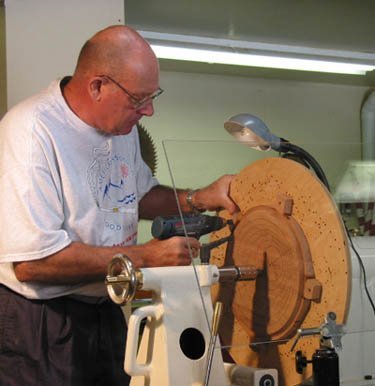
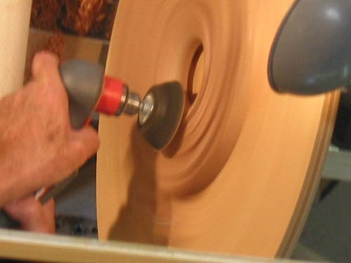
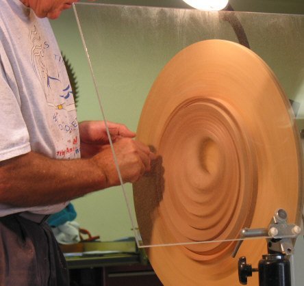
The part that is turned first is the back of the piece with the blank mounted in the most off-center position. The back side is only partially hollowed where the eventual off-center through-and-through hole will be located so that it can be entered and delineated from the front at a later stage without cutting into the jig-disk (#10). The blank is then re-attached face-out at the true center and the outer ring is cut approximately 60-70% deep (#11, 12). He keeps the step edges sharp and crisp. After each ring is cut, the blank is repositioned progressively further off-center (#13). When considerably off-center, he may attach lead weights with screws to counter balance the entire assembly to prevent vibration. With the large lathe and the relatively light Mahogany wood used in the demonstration , counterbalancing was not necessary.
The final cut on the lathe is through into the previously hollowed out back section (#14). He then sands the work with a combination of power sanding with the lathe on (#15) and lathe off, and hand sanding (#16), keeping the edges of the rings crisp. Sharp tools and technique are critical in minimizing tear-out of end grain. Sanding of each ring is best done prior to repositioning for the next cut, or if needed, the work can be replaced to a previous position using the index marks and pre-drilled holes. The final shape of the piece just prior to removal from the lathe is shown in #17.
At this point he uses a band saw to cut around the outer ring to remove the portion that was glued together. If a little glue has leaked between the inner parts he carefully separates the segments with a chisel. The outer edge is smoothed on a disk sander, and a router with a ½” cove bit is used to round over the back edges of each segment. Final hand sanding and application of finish comes next. The individual segments are mounted from behind with standoff spacers and screws onto a 3/16″ hardboard backing which he has painted “antique bronze.” The use of spacers between the turned segments and the backboard adds to the piece’s three-dimensional quality. Later, after several more hours of work in his own shop, he finished the piece (#18). As an added design detail, he also added texturing to one of the rings using a round burr and black leather dye.